Model application study
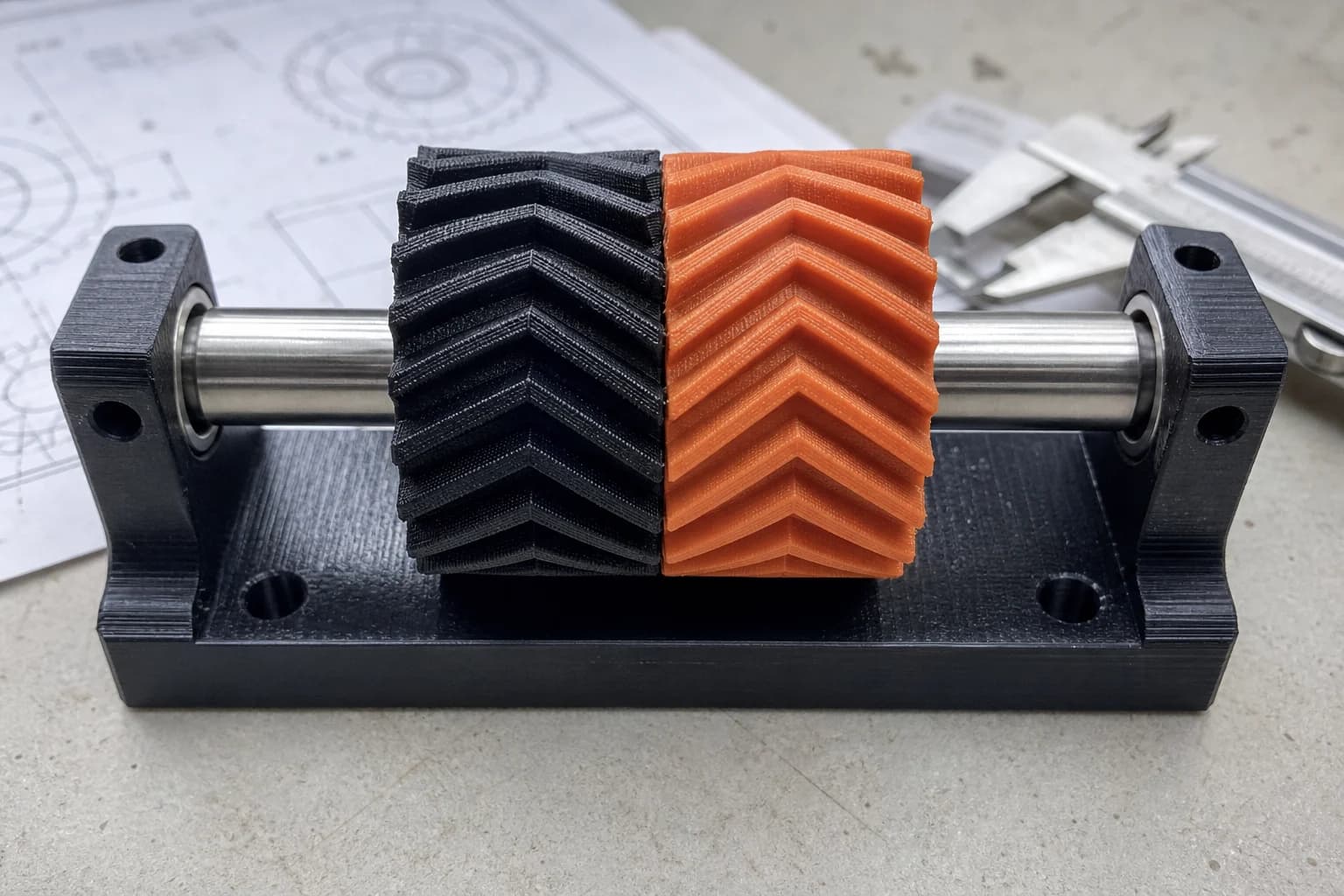
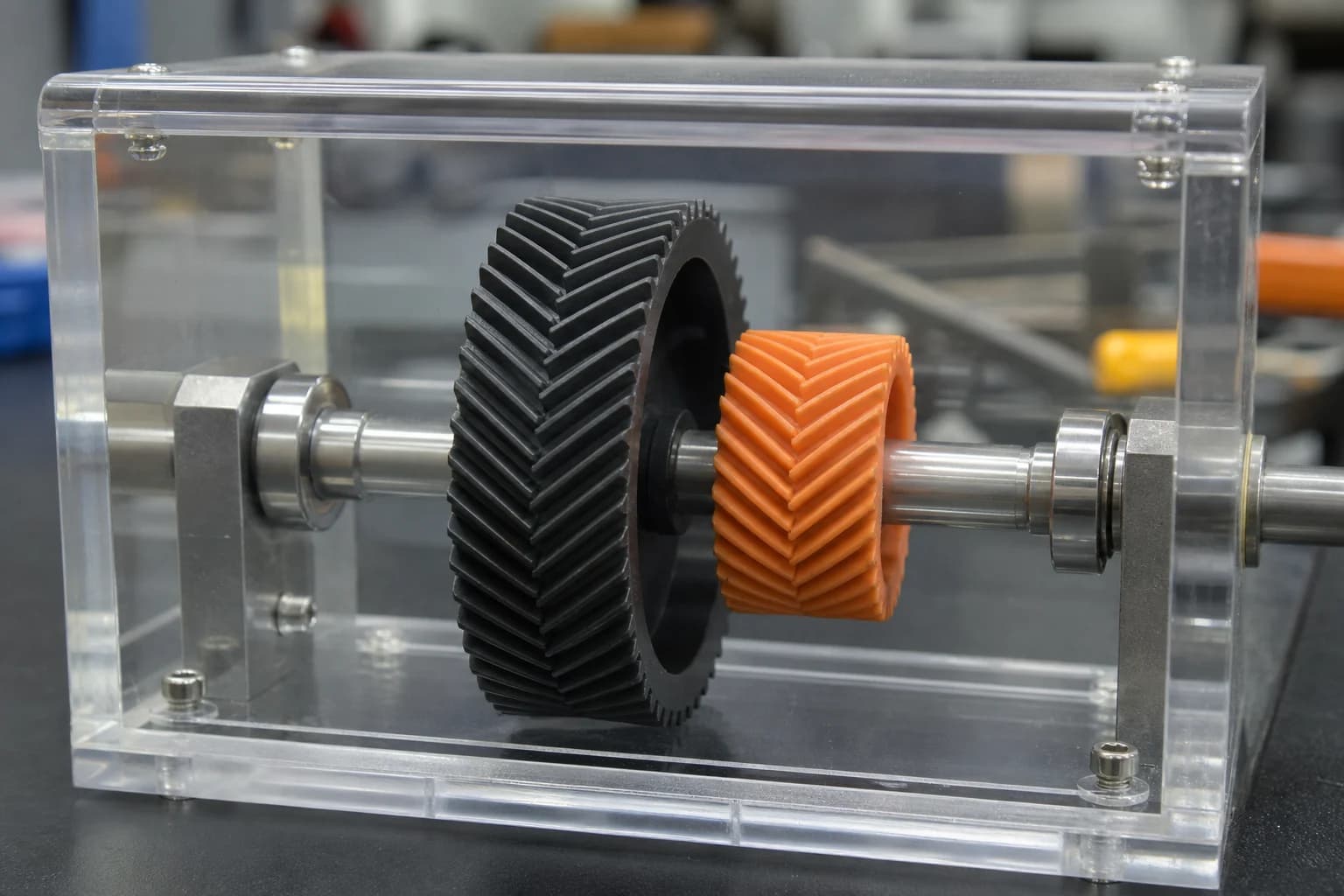
A printed herringbone gear pair for a smooth low-speed drive
How a module-2 herringbone gear uses opposed helices to cancel shaft thrust while keeping the whole part support-free.
The application
A compact demonstration drive needs quieter engagement than a plain spur pair without adding a thrust bearing for each shaft. Herringbone teeth solve both problems, but they are awkward to machine because a cutting tool needs somewhere to run out at the centre of the gear.
Constraints
- Both gears must share module, tooth count and helix geometry so the flanks mesh at the intended 48mm pitch diameter.
- The V at mid-face must meet cleanly without a machining-style centre groove.
- The printed part must stay within an orientation that gives each tooth continuous layer support.
Process
01
Set the working geometry
The model uses module 2, 24 teeth and a 20° helix, producing a 48mm pitch diameter and 52mm outside diameter.
02
Mirror the helix
Two 7mm helical halves meet at the 14mm face centre. Their axial loads oppose one another instead of pushing the shaft in one direction.
03
Print flat
With the bore vertical, the tooth twist advances gradually through the layers and needs no support. PETG suits a light drive; nylon or CF-nylon is the stronger option.
Design outcome
The published model gives a printable double-helical gear without the centre clearance groove a hobbed part normally needs. It is suitable for low-speed mechanisms and fit testing, with material and shaft support chosen around the actual load.
- Gear geometry
- Module 2, 24 teeth
- Pitch / outside diameter
- 48 / 52mm
- Face and bore
- 14mm / 6mm
- Helix angle
- 20° opposed